PicoCOM
| PicoCOM1 | PicoCOM1.2 | PicoCOM4 | PicoCOMA5 | PicoCOMA9X | PicoCOMA7 | |
| Status | No New Developments | Produktion | keine Neuentwicklungen | Production | Produktion | Production |
| CPU | - | - | - | - | - | - |
| Typ | ATMEL | NXP i.MX 6UL | Samsung ARM 926, 400 MHz | NXP Vybrid | NXP i.MX 6SoloX | NXP i.MX 6ULL |
| Kern | ARM 926 EJ | ARM Cortex-A7 | ARM 9 | ARM Cortex-A5 + Cortex-M4 | ARM Cortex-A9 + Cortex-M4 | ARM Cortex-A7 |
| Anzahl der Kerne | - | 1 | - | Single-/Dual-Core | 1 + M4 | 1 |
| Frequenz | 210 MHz | max. 696MHz | 400 MHz | max. 500MHz + 167 MHz | max. 1GHz + 200 MHz | max. 900MHz |
| L2-Cache | - | 128KB | - | 512KB | 256KB | 128KB |
| GPU | - | NEON | - | NEON FPU |
2D/3D NEON FPU |
- |
| Multimedia | CPU | - | CPU, 2D | - | - | - |
| Betriebssystem | - | - | - | - | - | - |
| Linux | 2.6 (Emlix Eval/ Pro) (uboot installed) |
Buildroot/Yocto (uboot installiert) |
2.6.37 (uboot installiert) |
Buildroot (uboot installiert) |
Buildroot Yocto (uboot installiert) |
Buildroot (uboot installed) |
| Windows | WCE 6.0 R3 (EBoot installed) |
WEC 2013 (Bootloader installiert) |
WCE 6.0 R3 (Bootloader installiert) |
WCE 6.0 WEC 7 WEC 2013 (Bootloader installiert) |
WEC 7 WEC 2013 (Bootloader installiert) |
WEC 7 WEC 2013 (EBoot installed) |
| Echtzeit | - | - | - | - | FreeRTOS | - |
| Speicher | - | - | - | - | - | - |
| Flash | 32MB+ | max. 1GB SLC NAND | 64MB+ | max. 512MB | max. 512MB SLC NAND | max. 512MB SLC NAND |
| RAM | 32MB+ | max. 512MB | 64MB+ | max. 512MB | max. 512MB DDR3L x16 | max. 1GB DDR3L x16 |
| Schnittstellen | - | - | - | - | - | - |
| SD-Karte | extern | 1x extern | extern | 1x extern | 1x extern | 1x extern |
| Ethernet | 10/ 100MB | 10/100Mb | 10/ 100MB | 2x 10/100Mb IEEE 1588 |
1-2x 10/100Mb IEEE 1588 |
1-2 10/100MB IEEE1588 |
| USB Host | 1-2 (2.0 FS) | 1x | 1-2 (1.1 FS) | 1-2x | 1x | 1x |
| USB Device | 0-1 (2.0 FS) | 1x | 0-1 OTG (2.0 HS) wird im Starterkit als RS232/ RS485 aufgeführt | 1x | 1x | 1x |
| CAN | 1 | 2x | 1 | 1-2x | 1-2x | 1-2x |
| UART | 1x mit Modemsignalen, Baudrate 115200 1x mit RTS/ CTS, max. Baudrate 115200 1x mit max. Baudrate 115200 |
6x | 1x mit RTC/ CTS, max. Baudrate 115200 1x mit RTS/ CTS, max. Baudrate 115200 1x mit max. Baudrate 115200 |
3x | 2-3x | 3x |
| I2C | 1 | 2x | 1 | 1-2x | 1x | 1-2x |
| SPI | opt. | 2x | opt. | 1x | 1x | 1x |
| Audio | 1x Audio Codec Line Out (L/ R) 1x Audio Codec Line In (L/ R) 3x Analog In (10Bit resolution) |
Line In/Out/analog | 1x Audio Codec Line Out (L/ R) 1x Audio Codec Line In (L/ R) |
Line In/Out | Line In/Out | Line In/Out |
| Digital I/O | - | - | - | - | max. 48 | max. 48 |
| Touch Panel | - | - | 4-Draht, analog resistiv | 4-wire, analog resistive PCAP-Touch via I2C |
4-wire, analog resistive PCAP-Touch via I2C |
4-wire, analog resistiver PCAP-Touch über I2C |
| RTC | - | - | - | - | - | externer IC |
| sonstige Schnittstellen | - | - | - | 2x 12Bit ADC | - | - |
| Display | - | - | - | - | - | - |
| RGB | - | - | - | 16/18bit | 16/18bit | 16/18 Bit |
| LVDS | - | - | extern | extern | - | external |
| Allgemein | - | - | - | - | - | - |
| Stromversorgung | +3,3V | +3,3V DC/ ±5% | +3,3V | +3,3V DC/ ±5% | +3,3V DC/ ±5% | +3,3V DC/ ±5% |
| Leistungsaufnahme | - | <1W typ. | - | 1W typ. | 2W typ. | 1.5W typ. |
| Betriebstemperaturbereich | -20°C - +85°C | 0°C - +70°C opt. -25°C - +85°C |
0°C - +70°C (-20°C - +85°C (optional)) | 0°C - +70°C opt. -20°C - +85°C |
0°C - +70°C opt. -40°C - +85°C |
0°C - +70°C opt. -25°C - +85°C |
| Größe | 40x50mm (LxB) |
40x50mm (LxB) |
40x50mm (LxB) |
40x50mm (LxB) |
40x50mm (LxB) |
40x50mm |
| Gewicht | - | ~15g | - | ~10g | ~15g | ~15g |
| Minimale Verfügbarkeit | - | 2035 | - | 2028 | 2035 | 2035 |
| PicoCOM1 | PicoCOM1.2 | PicoCOM4 | PicoCOMA5 | PicoCOMA9X | PicoCOMA7 |
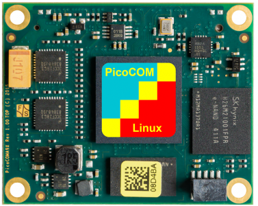
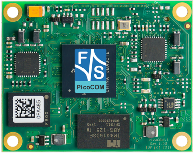
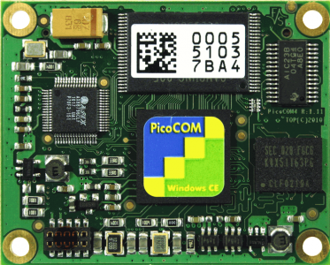
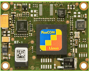
Die PicoCOM Familie bietet dem Kunden kompakte und preisgünstige COM Module.
Die Module sind zueinander kompatibel. Unser Ziel ist es mit den PicoCOM Modulen so viele Standardschnittstellen als möglich anzubieten, die alle vom integrierten OS unterstützt werden. Dies ermöglicht die schnelle Erstellung der Applikationssoftware, ohne dass ein tiefer fundiertes Hardware-Wissen von Nöten ist. Das Modul in die umgebende Hardware zu integrieren, ist ebenfalls unkompliziert.
Aufgrund dessen ist die Spannungsversorgung der CPU schon direkt auf dem Board vorhanden und das Board wird mittels eines robusten 80pol Steckverbinders auf das Basisboard des Kunden aufgesteckt. Nur einige zusätzliche Schnittstellentreiber (RS232, Ethernet-Transformator ) sind noch notwendig. Alle Module dieser Produktfamilie haben dieselbe Größe (40mm x 50mm) und verwenden den gleichen Steckverbinder, bei welchem die erste Hälfte der Anschlussstifte festgelegte Signale und die zweite modulspezifische Schnittstellen enthält. Auf diese Weise ist es jederzeit möglich auf in Zukunft folgende Module dieser Familie umzusteigen (UpGrade zu Modulen mit höherer Rechenleistung und mehr Speicher oder aber auch auf neuere, preiswertere Module).


